%20(1).png?width=250&height=100&name=Knowledge%20Base%20(500%20x%20200%20px)%20(1).png)

Important Safety Notice

It is the responsibility of the person installing the electrical equipment to ensure that the installation meets the requirements of the IET wiring regulations and is therefore ‘fit for purpose’. Any other regulations applicable to the equipment being installed such as the machinery directive and current health and safety legislation must also be adhered to. Terminals, including factory fitted, should be checked periodically to ensure correct tightness. All installations must be protected by an appropriate external disconnect device, therefore a 32A Circuit Breaker compliant to IEC 60947-2 must be installed, marked as the disconnecting device for the equipment & must be suitably located and easily reached. CAUTION is necessary when installing the device close to where the exclamation symbol (example on the left) is placed on the product and reference to the manual should be made. Installers must ensure wiring to and from the isolator is specified with cabling rated for temperatures of a minimum of 150°C.

Factors such as correct selection of components, cable sizing, protective devices and earth bonding are all critical and should be checked prior to full testing and power-up. Installers must check the manual before determining the Temperature rating of the cables to be connected to the terminals. Installers must also take note and use the protective earth (ground) terminal denoted by the symbol to the left which MUST be connected to an external conductor for protection against electrical shock in case of a fault with a minimum rating of 32A (VC4-P3-32). It is highly recommended for Installers to use insulated plastics IP65/IP68 rated glands when connecting into this product. Brass glands may be used but installers must follow the instructions below. For clarity note that brass glands may only be fitted via the bottom knock-outs and only when the protective shield is utilised.
Procedure to Remove the Cover
Equipment must be placed in a safe state before access.
Note that to function correctly this product must be wired to a device that requires a neutral. Therefore it is not suitable for some scenarios (such as balanced three phase motor loads or systems with a delta configuration; this list is not exhaustive). Installers must check suitability prior to commencing installation.
All installations must be protected by an appropriate external disconnect device. Therefore turn off or disconnect the 32A Circuit Breaker upstream of the Verv Smart Isolator at the distribution board by turning off or removing the disconnecting device. Secure the distribution board (eg: with a padlock) to prevent accidentally re-establishing power to the Verv Smart Isolator.
Ensure the switch is in the OFF position
Unscrew the cover screws, switch handle screw & remove
Once wiring is completed replace the switch and secure in position with the fixing screws (taking care not to over tighten - recommended tightening torque 0.5Nm)
After wiring ensure the profile orientation of the actuating spindle & knob shaft are in the same position
Replace the cover & take care not to overtighten the screws (recommended tightening torque 0.5Nm)
Do not install using power driven screwdrivers.
Gland Selection & Installation
It is possible to use brass glands in certain circumstances, for example if armoured cable is specified, and only by adhering to the following instructions. Brass glands may be used only in the bottom knock outs and only when the provided shield is in place & correctly utilised (see photo below).
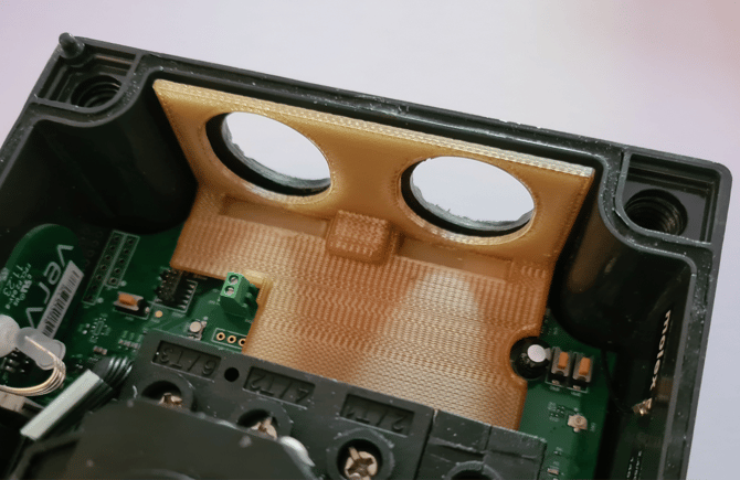
The protective shield (above in tan) must be used. Do not proceed to power up or operate the isolator if any component in the product is damaged or missing.
The Verv Smart Isolator can accept 20mm or 25mm brass glands. There are additional requirements for using 25mm brass glands. Suitable washers must be installed between the isolator enclosure face and the cable gland.
Please also note the following drilling instructions for 25mm brass cable glands. Hole centres must be drilled 3mm above the knockout centreline. Drill the hole with the centre offset 3mm above where it is marked on the knockout as shown in the diagram below.
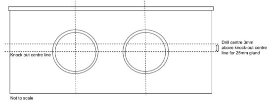
Important: Please note that a suitable drill bit or jig must be used to prevent damage to the electronic circuitry when drilling through the knockouts.
Device Operation
The Verv Smart Isolator monitors energy utilisation and constantly watches out for equipment anomalies by analysing the harmonic waveforms generated by the equipment it is attached to. It is a direct replacement for a conventional rotary isolator of the same rating. The device communicates with Verv’s cloud infrastructure over Wifi or Cellular Radio (depending on version).
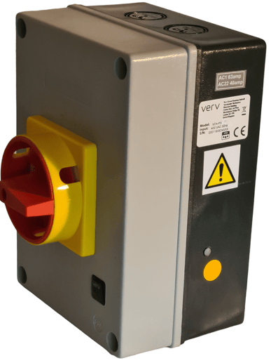
You will notice that the exterior of the unit is very similar to a conventional isolator apart from the orange touch switch & LED, which is a status indicator light on the lower right hand side of the unit as you look at it. The touch sensor is multifunction:
- A short touch (touch and release within 1s) will make/break the pilot relay signal for external contractors (which must be supplied separately)
- A longer touch (touch and release after 10s) will put the unit into Bluetooth pairing mode
- An even longer touch (more than 20s) will soft reset the device
In operation, the status indicator light will also produce different colour variations & flashes depending on the status of the unit:
- Flashing Red indicates that the unit is booting or processing (it is not an error)
- Flashing Purple usually indicates the unit is not connected to the internet, or does not have the correct credentials for wifi
- Solid purple indicates that the unit is connected but is unable to upload its data via the internet
- Solid White indicates that the unit is connected and fully operational
- Flashing Blue/Red indicates that the unit is receiving programming (known as a firmware update) from the internet
- Flashing Blue indicates the unit is in Bluetooth mode and ready to accept new parameters
- Solid Red indicates that the unit has signalled the contactors to be OFF
On power up the unit takes a few seconds to boot and the LED will flash Red during this time which means the device is busy and the multi-function switch cannot be used.
Details of the appropriate glands to use for your specific requirement are provided in the accompanying datasheet or via this link LB634P.pdf
Installation
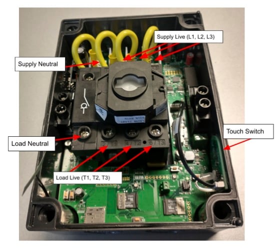
Cable entries for supply live (L1, L2, L3) and supply neutral and load live (T1, T2, T3) and load neutral must be made from the bottom using the tan coloured shield provided. Ensure the SD cards (and SIM if there is one) are correctly seated as they can move in transit. Note that on the supply side connection MUST be made to the screw terminals on the PCB board as indicated, NOT the rotary isolator itself.
PLEASE READ THE IMPORTANT SAFETY NOTICES ABOVE BEFORE INSTALLING
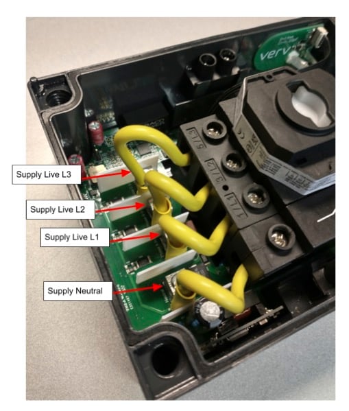
The diagram above shows a close-up of the supply live (L1, L2, L3) and supply neutral screw terminals on the PCB. DO NOT wire supply into the rotary switch.
Onboard your Isolator
Once installed the Smart Isolator must be “onboarded” to the analysis platform with a phone app called Verv Connect, which is available either on Google Play or the Apple App Store, so go ahead and download the app most suitable for your device. The app itself also replicates much of the functionality of the analysis platform.

Additional check points
- Check sd cards are secured properly before installation
- After installation, power up the isolator
- Before putting the enclosure lid back, confirm LED2 (bottom right) is flashing green
- No activity on LED2 -> sd card (SD2 - bottom right) is not fitted properly
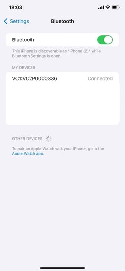
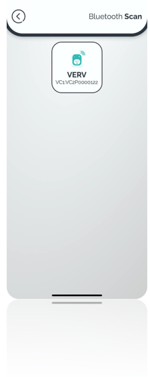
Scan and find your device
To be able to scan for devices the Verv Connect application needs access permissions to your device’s Bluetooth. On android, devices having location permission is also a requirement.
The first time you try to scan for a device, the application asks for your permission, please select “OK” when the message is shown. If you do not give the permission the first time, you need to do it manually, below there is an explanation on how you can give access manually.
iOS
You must navigate to Settings->Verv->Click on Bluetooth.
Android
You must navigate to Settings->Apps-> Apps->Verv->Permissions.

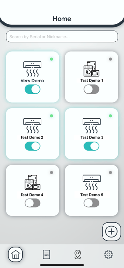
Once you have granted access to Bluetooth, the mobile application you can find your devices and display them on the screen.
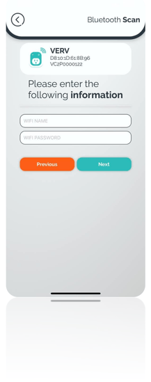
Input the Required Information
The next step is to enter the information about the equipment that the Verv Isolator is attached to. Please make sure you enter the right information.

Setup Wi-Fi
The last step is to input the Wi-Fi name and password that the Verv Connect must use. Please make sure you enter the right information as the name and the password are case sensitive.
Changing Wi-Fi information
To change the Wi-Fi settings on a device you need to put the device into Bluetooth mode and do the onboarding process again, the information about your device won’t change, only the new Wi-Fi information will be written on the device.
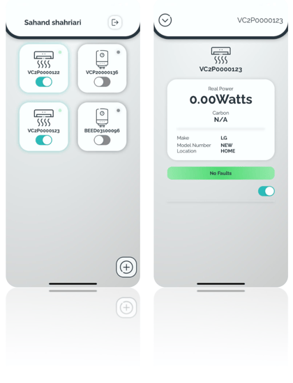
You can look at your equipment once you finish the onboarding process.
|
Approvals |
CE |
|
International |
Switch-disconnector according to IEC/EN 60947-3 EMC according to EN IEC 61326-1: 2021, ETSI EN 301 489-17 V3.1.1 Safety according to IEC 61010-1:2010, IEC, 61010-1:2010/AMD1:2016 |
|
Climate Proofing |
Damp heat, constant, to IEC 60068-2-78 Damp heat, cyclic, to IEC 60068-2-30 |
|
Ambient temperature (enclosed) |
-25°C - +40°C |
|
Location & Usage |
Indoor or outdoor. NOT for use in wet locations |
|
Overvoltage Category |
Category 3 |
|
Pollution Degree |
2 |
|
Mains Supply Voltage Fluctuation |
+/-10% |
|
Degree of Ingress Protection |
IP65 |
|
Operational Temperature |
-20°C to +40°C |
|
Operational Humidity |
Up to 85% |
|
Maximum Operational Altitude Above Sea level |
2000m |
|
Cleaning & Decontamination |
Do not use surfactants, use warm damp cloth only |
|
Protection Impairment (IEC 60950) |
Protection for this device as described will be impaired if installed or used in a manner not specified by the manufacturer |
|
Data |
Range |
Units |
VC4-P3-32 |
|
Rated Operational Voltage |
|||
|
IEC & EN |
Volts |
VAC |
230/400 |
|
Rated uninterrupted current |
Iu |
A |
32 |
|
Rated Operational Current Ie |
|||
|
IEC & EN |
AC-22A AC-21A AC-1 |
A |
25 32 32 |
|
Rated Operational Power AC-23A (50-60Hz) |
|||
|
IEC & EN |
3 Phase (230/400) kW |
23 |
|
|
Terminal Specification |
|||
|
Single/Multiple strand wire |
mm2 |
2.5 min 10 max |
|
|
Fine strand with sleeve |
mm2 |
2.5 min 10 max |
|
|
American wire gauge |
AWG |
6 |
|
|
Tightening torque for terminal screw |
Nm |
1.7 |
|
|
Mechanical |
|||
|
Number of Poles |
4 |
||
|
Mounting |
Surface Mounting |
||
|
Locking Facility |
Lockable in the 0 (Off) position |
||
|
Stop Function |
Emergency switching off function with red rotary handle and yellow locking ring |
||
|
Cloud & Data Services |
|||
|
Cloud Storage |
AWS |
||
|
API |
REST API, MQTT & FTP |
||
|
Communications |
|||
|
Transport |
|||
|
Wifi 2.4GHz 802.11 b/g/n up to 150 Mbps |
YES |
||
|
Bluetooth v4.2 BR/EDR and Bluetooth LE |
YES |
||
|
Cellular 3G, 4G-LTE, NB-IOT |
YES |
||
|
Power Quality Calculations & Logging |
|||
|
Voltage Resolution (16-bit, software upgradable to 24-bit) |
KHz |
8 |
|
|
Current Resolution (16-bit, software upgradable to 24-bit) |
KHz |
8 |
|
|
Power Factor Resolution |
KHz |
8 |
|
|
Real Power Resolution |
KHz |
8 |
|
|
Apparent Power Resolution |
KHz |
8 |
|
|
Reactive Power Resolution |
KHz |
8 |
|
|
Total Harmonic Distortion |
%/dB |
|
|
|
Predictive Maintenance |
|||
|
Appliance Dependent |
Eg: Aircon Filter Blockage |
||
|
For Aircon / ASHP |
Outdoor Unit Filter Blockage, Splitter Filter Blockage, Compressor Failure, Capacitor Failure, Refrigerant Leak |
||
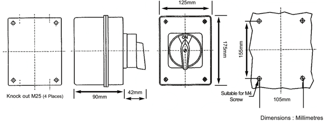
Dimensions & Mounting
VC4-P3-32