%20(1).png?width=250&height=100&name=Knowledge%20Base%20(500%20x%20200%20px)%20(1).png)
Important Safety Notice

It is the responsibility of the person installing the electrical equipment to ensure that the installation meets the requirements of the IET wiring regulations and is therefore ‘fit for purpose’. Any other regulations applicable to the equipment being installed such as the machinery directive and current health and safety legislation must also be adhered to. Terminals, including factory fitted, should be checked periodically to ensure correct tightness. All installations should be protected by an appropriate external disconnect device compliant with BS EN IEC 61010 suitably specified for the circuit, and marked legibly for the disconnection of this device, and which must be easily accessible at all times. CAUTION is necessary when installing the device close to where the exclamation symbol (to the left) is placed on the product.

Factors such as correct selection of components, cable sizing, protective devices and earth bonding are all critical and should be checked prior to full testing and power-up. Installers must take note and use the protective earth (ground) terminal denoted by the symbol to the left which MUST be connected to an external conductor for protection against electrical shock in case of a fault with a minimum rating of 32A (VC2-P1-32).
Device Operation
The Verv Smart Isolator monitors energy utilisation and constantly watches out for equipment anomalies by analysing the harmonic waveforms generated by the equipment it is attached to. It is a direct replacement for a conventional rotary isolator of the same rating. The device communicates with Verv’s cloud infrastructure over Wifi or Cellular Radio (depending on version).
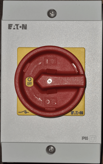
You will notice that the exterior of the unit is very similar to a conventional isolator apart from the pushbutton, which is also a status indicator light on the lower right hand side of the unit as you look at it. This pushbutton is multifunction:
- A short push (push and release within 1s) will make/break the contactors (if fitted, dependent on model)
- A longer push (push and release after 10s) will put the unit into Bluetooth pairing mode
In operation, the status indicator light will also produce different colour variations & flashes depending on the status of the unit, explained further below.
- Flashing Purple indicates the unit is not connected to the internet, or does not have the correct credentials for wifi
- Solid purple indicates that the unit is connected but is unable to upload its data via the internet
- Solid White indicates that the unit is connected and fully operational
- Flashing Blue/Red indicates that the unit is receiving programming (known as a firmware update) from the internet
- Flashing Blue indicates the unit is in Bluetooth mode and ready to accept new parameters
- Solid Red: Wi-Fi successfully connected, Shadow connected, Relay turned OFF
Of the four knockouts in the plastic enclosure, all except the bottom right are usable for a variety of cable entry/exit scenarios. Details of the appropriate glands to use for your specific requirement are provided in the accompanying datasheet (see link below).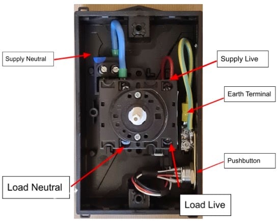
Figure 4: The unit comes partially pre-wired to the control board
As can be seen from the above diagram the cable configuration is such that the supply live and neutral terminals (denoted by a brown and blue spot (left most terminal) on the top of the unit respectively) are best accessed from one of the top cable entries and the load live and neutral (denoted by a brown and blue spot respectively on the bottom of the switch) are best accessed from the bottom left cable entry. Whilst this is the optimal configuration, how you access the isolator will be down to each individual installation.
Leave sufficient excess cable to make the connection. It is good practice to pull both cables through and prepare them prior to making any connections.
Earth connections are made utilising the Earth terminal bar on the right hand side of the unit as you look at it. Earth is wired ‘straight through’ - so wire the supply and load earths together on the Earth terminal bar (mid-left of shot figure 4). The earth terminal bar is also sometimes marked with a green dot on the sidewall of the enclosure.
Ensure that there is an earth tag to the earthing bar from the barrel of the momentary switch. This is often marked with a yellow dot on the sidewall of the enclosure.
Switching Control
The Verv Smart Isolator (Single Phase) can switch loads using an onboard relay. The on/off feature can be accessed either by using the pushbutton on the side of the unit (the LED will display RED when the relay is disconnected). By briefly depressing the pushbutton the relay will disconnect. Once in this mode by briefly depressing the pushbutton again the relay will reconnect and the LED will return to white. The on/off feature can also be accessed on the phone app and the web portal.
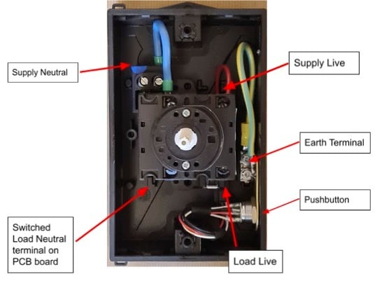
Figure 1: Switched Load Neutral terminal located on PCB behind tab and underneath rotary switch
To use switching functionality the blue conductor from the PCB to the supply neutral terminal on the rotary switch disconnector must be removed completely and a replacement conductor of the same rating connected from the switched load neutral terminal on the PCB board (which is located underneath the rotary switch disconnector, see picture below) to the supply neutral terminal on the rotary switch disconnector.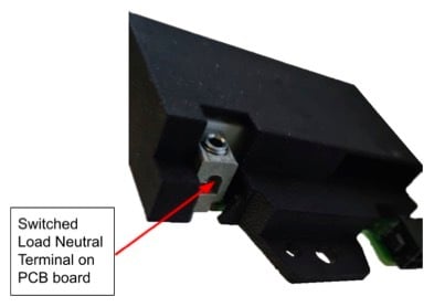
Figure 2: Switched Load Neutral terminal located on PCB. Rotary switch removed in photo for clarity
Additional Check Points
- Check sd cards are secured properly before installation
- After installation, power up the isolator
- Before putting the enclosure lid back, confirm LED2 (bottom right) is flashing green
- No activity on LED2 -> sd card (SD2 - bottom right) is not fitted properly
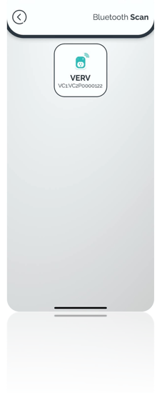
Scan and find your device
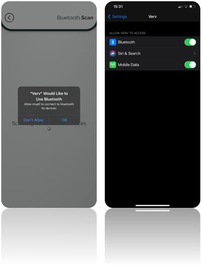
To be able to scan for devices Verv Connect application needs access permission to your device Bluetooth. On android devices having location permission is also a requirement.
The first time you try to scan for a device, the application asks for your permission, please select “OK” when the message is shown. If you do not give the permission the first time, you need to do it manually, below there is an explanation on how you can give access manually.
iOS
You must navigate to Settings->Verv->Click on Bluetooth.
Android
You must navigate to Settings->Apps-> Apps->Verv->Permissions.
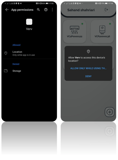
Once you have granted access to Bluetooth, the mobile application you can find your devices and display them on the screen.
Input the Required Information
The next step is to enter the information about the equipment that the Verv Isolator is attached to. Please make sure you enter the right information.

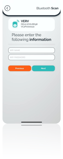
Setup Wi-Fi
The last step is to input the Wi-Fi name and password that the Verv Connect must use. Please make sure you enter the right information as the name and the password are case sensitive.
Changing Wi-Fi information
To change the Wi-Fi intimation on a device you need to put the device into Bluetooth mode and do the onboarding process again, the information about your plug won’t change, only the new Wi-Fi information will be written on the device. This is a temporary solution and on the next update you will have a different panel to change the Wi-Fi.
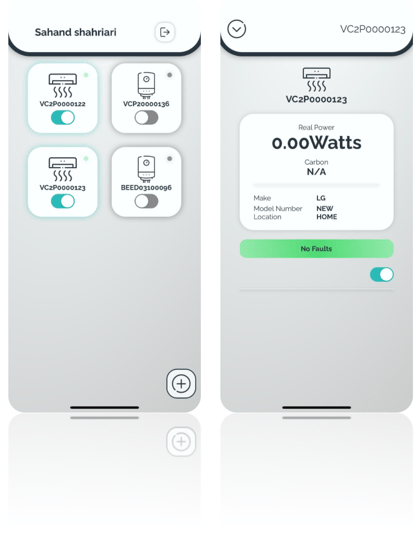
You can look at your equipment once you finish the onboarding process.
Note:
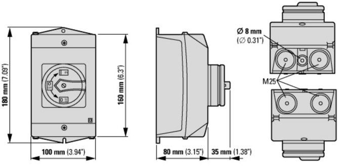
More information regarding the electrical specifications of the switchgear, drill template & compatible gland options can be found here in the product datasheet.
|
Approvals |
CE |
|
International |
Switch-disconnector according to IEC/EN 60947-3 |
|
Climate Proofing |
Damp heat, constant, to IEC 60068-2-78 Damp heat, cyclic, to IEC 60068-2-30 |
|
Ambient temperature (enclosed) |
-25°C - +40°C |
|
Location & Usage |
Indoor or outdoor. NOT for use in wet locations |
|
Overvoltage Category |
Category 2 |
|
Pollution Degree |
2 |
|
Mains Supply Voltage Fluctuation |
+/-10% |
|
Degree of Ingress Protection |
IP65 |
|
Operational Temperature |
-20°C to +40°C |
|
Operational Humidity |
Up to 85% |
|
Maximum Operational Altitude Above Sea level |
2000m |
|
Cleaning & Decontamination |
Do not use surfactants, use warm damp cloth only |
|
Protection Impairment (IEC 60950) |
Protection for this device as described will be impaired if installed or used in a manner not specified by the manufacturer |
|
Data |
Range |
Units |
VC2-P1-32 |
VC4-P3-32 |
VC4-P3-63 |
|
Rated Operational Voltage |
|
||||
|
Rated uninterrupted current |
Iu |
A |
32 |
32 |
63 |
|
Short Circuit Rating (Fuse) |
Amps |
gG/gL |
35 |
50 |
80 |
|
Supply Voltage Range |
Volts |
VAC |
100 - 240 |
100 - 240 |
100 - 240 |
|
Rated frequency |
Hertz |
Hz |
50 - 60 |
50 - 60 |
50 -60 |
|
Safe isolation to EN 61140 |
|
||||
|
Between the contacts |
Volts AC |
V |
440 |
440 |
440 |
|
Current heat loss per contact at Ie |
Watts |
W |
1.1 |
1.8 |
4.5 |
|
Current heat loss per auxiliary circuit at Ie (AC-15/230V) |
CO |
1.1 |
TBA |
4.5 |
|
|
Maximum switched load current via relay terminal |
A |
16 |
N/A |
N/A |
|
|
Recommended Cable Specification |
|
||||
|
Solid or stranded |
mm2 |
1x (1 - 6) 2 x (1 - 6) |
1x (1.5 – 6) 2x (1.5 – 6) |
1x (2.5-35) 2x (2.5-16) |
|
|
Flexible with Ferrules to DIN 46228 |
mm2 |
1x (0.75-4) 2x (0.75-4) |
1 x (1 - 4) 2 x (1 – 4) |
1x (1-25) 2x (1.5-10) |
|
|
Terminal Screw |
M4 |
M4 |
M6 |
||
|
Tightening torque for terminal screw |
Nm |
1.6 |
1.6 |
4 |
|
|
Mechanical |
|
||||
|
Number of Poles |
2 |
3 |
6 |
||
|
Mounting |
Surface Mounting |
||||
|
Locking Facility |
Lockable in the 0 (Off) position |
||||
|
Stop Function |
Emergency switching off function with red rotary handle and yellow locking ring |
||||
|
Mechanical Shock Resistance |
g |
12 |
15 |
15 |
|
|
Cloud & Data Services |
|||||
|
Cloud Storage |
AWS |
||||
|
API |
REST API, MQTT & FTP |
||||
|
Communications |
|||||
|
Transport |
|||||
|
Wifi 2.4GHz 802.11 b/g/n up to 150 Mbps |
YES |
YES |
YES |
||
|
Bluetooth v4.2 BR/EDR and Bluetooth LE |
YES |
YES |
YES |
||
|
Cellular 3G, 4G-LTE, NB-IOT |
NO |
YES |
YES |
||
|
Power Quality Calculations & Logging |
|
||||
|
Voltage Resolution (16-bit, software upgradable to 24-bit) |
KHz |
10 |
8 |
8 |
|
|
Current Resolution (16-bit, software upgradable to 24-bit) |
KHz |
10 |
8 |
8 |
|
|
Power Factor Resolution |
KHz |
10 |
8 |
8 |
|
|
Real Power Resolution |
KHz |
10 |
8 |
8 |
|
|
Apparent Power Resolution |
KHz |
10 |
8 |
8 |
|
|
Reactive Power Resolution |
KHz |
10 |
8 |
8 |
|
|
Total Harmonic Distortion |
%/dB |
|
|||
|
Predictive Maintenance |
|||||
|
Appliance Dependent |
Eg: Aircon Filter Blockage |
||||
|
For Aircon / ASHP |
Outdoor Unit Filter Blockage, Splitter Filter Blockage, Compressor Failure, Capacitor Failure, Refrigerant Leak |
||||
Dimensions & Mounting
VC2-P1-32